
Reputation: 1267
Circular led loop in Atmega2560 using Assembly
I'm working on a simple LED project using Atmega2560 microcontroller. The LEDs should rotate in a circular pattern respectively.
DEF consts:
LED_AMNT : How many LEDs will turn
LED_DATA : Which LEDs will work
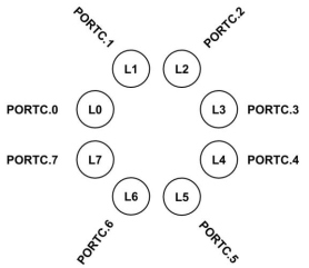
Led layout design :
LED_AMNT = 1 Animation
LED_AMNT = 2 Animation
The code I wrote is working a bit wrong.
1) L7 and L0 not working together. The first bit shifts to 0 at the end.
Step 0 : L0 and L1 -> 0000 0011
...
Step 6 : L6 and L7 -> 1100 0000
Step 7 : L7 and L0 -> 1000 0001 (must be such)
Step 7 : L7 and L0 -> //Skipped to Step 0

2) When I click the LED_AMNT_INCREASE button, the number of LEDs is increasing but when the tour is over. It does not increase instantly. I'm waiting for the current tour to end. (when 0x80 changes to 0x01)
I wrote a simple program, which looks as follows:
.def LEDS = R16

.def LED_DIRECTION = R17
.def LED_AMOUNT = R19
.def LED_DATA = R21

.org 0
    rjmp MAIN

MAIN:
    ldi LEDS, 0xFF          ; 0xFF = 1111 1111

    ldi LED_DATA, 0x01      ; PORTC load register
    ldi LED_DIRECTION, 0x01 ; 0x01 ==> Right, 0x00 ==> Left
    ldi LED_AMOUNT, 0x01    ; total active led count

    out DDRC, LEDS          ; make PORTC's all pins to output
    sbi PORTB, 0
    sbi PORTB, 1
    sbi PORTB, 2

LOOP_MAIN:
    out PORTC, LED_DATA
    call DELAY
    call DELAY
    call DELAY
    call DELAY
    call DELAY

    sbis PINB, 0
    rjmp BUTTON_CLICK_DIRECTION

    sbis PINB, 1
    rjmp BUTTON_CLICK_AMOUNT

    cpi LED_DIRECTION, 0x01
    brne LOOP_RIGHT

    LOOP_LEFT:
    lsl LED_DATA
    cpi LED_DATA, 0x80
    brne LOOP_MAIN
    LEFT_RESET:
    lsl LED_DATA
    out PORTC, LED_DATA
    call DELAY
    mov LED_DATA, LED_AMOUNT
    ;mov LED_DATA, LED_AMOUNT
    ;brne LEFT_RESET
    rjmp LOOP_MAIN

    LOOP_RIGHT:


    LOOP_MAIN_END:
    rjmp LOOP_MAIN

BUTTON_CLICK_DIRECTION:
    cpi LED_DIRECTION, 0x00
    brne it_is
    it_isnt:
    ldi LED_DIRECTION, 0x01
    rjmp yon_end
    it_is:
    ldi LED_DIRECTION, 0x00
    yon_end:
    rjmp LOOP_MAIN

BUTTON_CLICK_AMOUNT:
    rol LED_AMOUNT
    cpi LED_AMOUNT, 0x1F
    breq amount_reset
    rjmp amount_end
    amount_reset:
    ldi LED_AMOUNT, 0x01
    amount_end:
    mov LED_DATA, LED_AMOUNT
    rjmp LOOP_MAIN

DELAY:
   push r16
   push r17

   mov r16,0x40
   ldi r17,0x00
   ldi r18,0x00
_w0:
   dec r18
   brne _w0
   dec r17
   brne _w0
   dec r16
   brne _w0
   pop r17
   pop r16
   ret
Upvotes: 1
Views: 825
Answers (1)

Reputation: 12620
You basically want to rotate the byte's value. You can do this via the following pseudo code:
// Check if most significant bit is set:
if ( (LED_DATA & 0x80) != 0 ) {
  LED_DATA = LED_DATA << 1 | 1; // Copy msb to lsb after shift.
} else {
  LED_DATA = LED_DATA << 1;
}
In assembler, you can also just copy the carry bit after the shift to the LSB:
lsl LED_DATA
adc LED_DATA, ZERO_REG ; add 0 + carry (either 0 or 1) to LED_DATA
or, more verbosely:
lsl LED_DATA
brcc SHIFT_0_IN ; if carry not set, the MSB was not set, so skip setting the LSB
ori LED_DATA, 1 ; set LSB to 1

SHIFT_0_IN:
  ; keep LSB as 0 -> do nothing, just continue

...
The same also works for rotation in the other direction:
Just shift right (LSR), and replace ori LED_DATA, 1 with ori LED_DATA, 0x80, setting the MSB instead of the LSB.
To update the running pattern, you'll have to look at the current state to find the bit to set.
This can be done in a 'smart' way: Before shifting LED_DATA check if you should add another LED bit. If no, just shift as above. If yes, remember the old value of LED_DATA, shift LED_DATA as above, and then set LED_DATA = LED_DATA | prevLedData.
An 'easy' way could be to use four different patterns, like LED_DATA_1 = 0x00000001, LED_DATA_2 = 0b00000011, LED_DATA_3 = 0b00000111, LED_DATA_4 = 0b00001111. In each step you rotate all of the four values and depending on how many LEDs you actually need to turn on you output the corresponding value from one of the four registers. You'd need another register to store how many LEDs should be lit at the moment which changes each time the button is pressed from 1 through 4 (or 0 through 3) and back to 1 (or 0).
Upvotes: 2
Related Questions
- Ring counter avr assembler,
- Cant get loop working in ASSEMBLY x64 nasm
- Programming AVR in C
- AVR LED on-off program in assembly using buttons
- Creating a loop within an assembly macro - IAR ARM
- Assembly code in GCC is not being compiled in Atmel Studio for AVR environment
- AVR Assembly not doing what I intend it to Do
- Atmega128 Assembly Project
- Loops in Assembly
- Assembler - loop with ECX